Homemade battery recovery circuit [Eng+Spa]
Greetings, Hive DIY community, I hope you're in high spirits and that this new week will be productive for sharing interesting posts with us.
I'm taking this opportunity to fulfill my promise in my previous UPS repair post: I promised to explain how to make and use a simple homemade battery recovery unit.
At that time, I built a test recovery circuit just to verify if the old battery from the UPS I was working on could be recycled.
An important clarification: If you work with or are going to handle these types of batteries, you must be aware of:
- Wear protective glasses.
- Wear a face mask or respirator.
- Ensure the work area is well ventilated.
These batteries contain acid and can cause damage if it gets on your skin or you breathe the fumes released during the repair process.
Be aware of the cost of the batteries; if they're very cheap, it's not worth all the work. In my country, they sell batteries for almost the same price as buying a UPS, which is why I take the trouble to recycle them.
A discharged rechargeable battery, in good condition, should have a value close to half of its maximum charge when checked with a tester.
If the battery is 12 volts DC, it should read around 6 volts DC. Reading 1 volt DC or less is a very poor indicator of your chances of recovery.
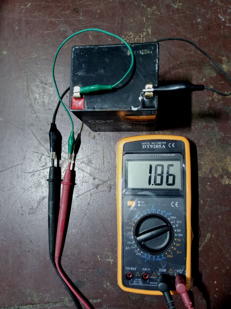
Less than 2 volts DC is not very encouraging.
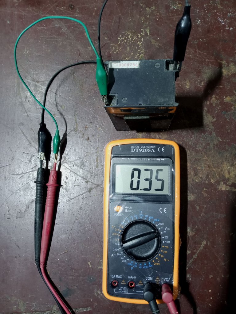
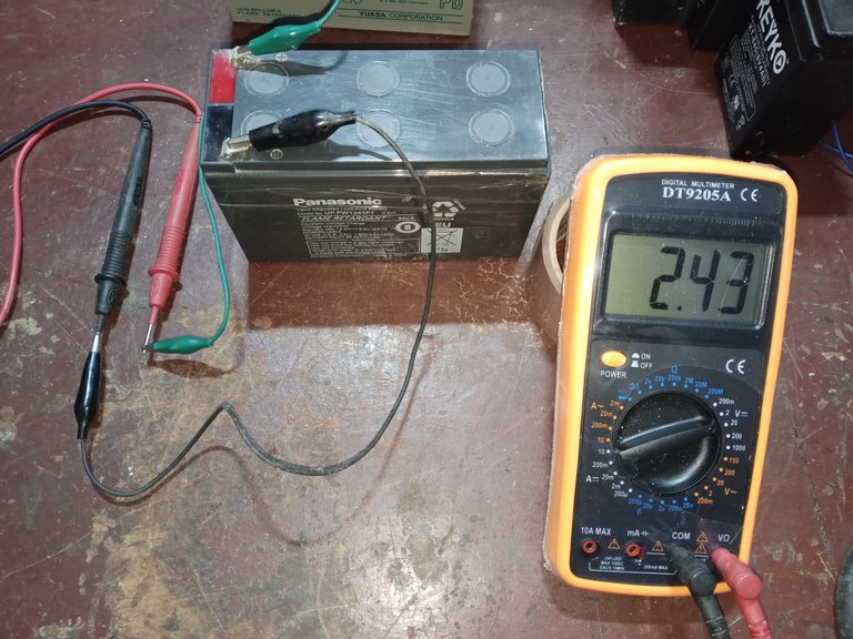
Finally, I found a battery with more than 2 volts DC in my storage unit. I'll use it for this post. It's not at the minimum acceptable value, but it will help me explain the details.
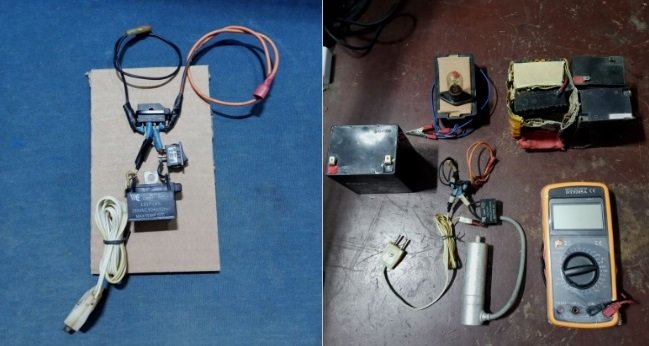
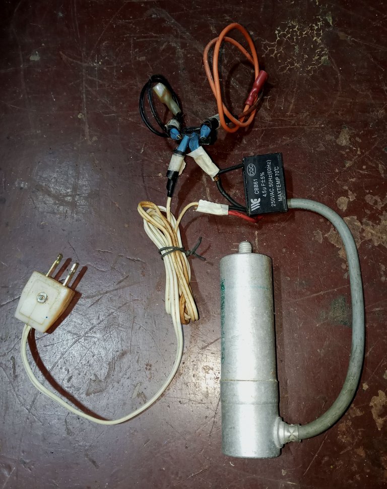
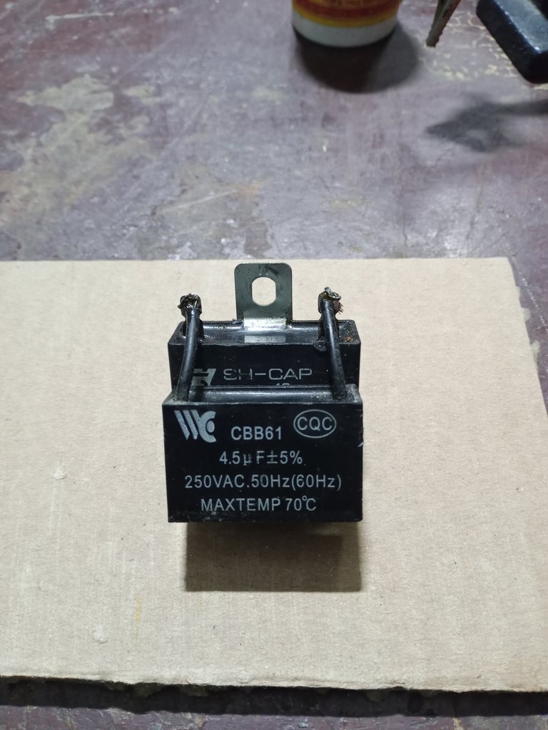
As for the electrical circuit, it's very basic. I used a bridge rectifier I recycled from an old stereo system, and capacitors and wires recovered from recycled fan motors.
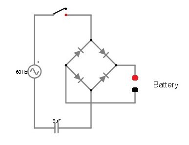
To work with UPS batteries, using an 8 microfarad capacitor is sufficient. For larger car batteries, I've seen 45 UF capacitors used.
The problem is that I only had one capacitor, either very large or very small.
I had a 15 UF capacitor and 4 UF and 5 UF capacitors.
 |  |
|---|---|
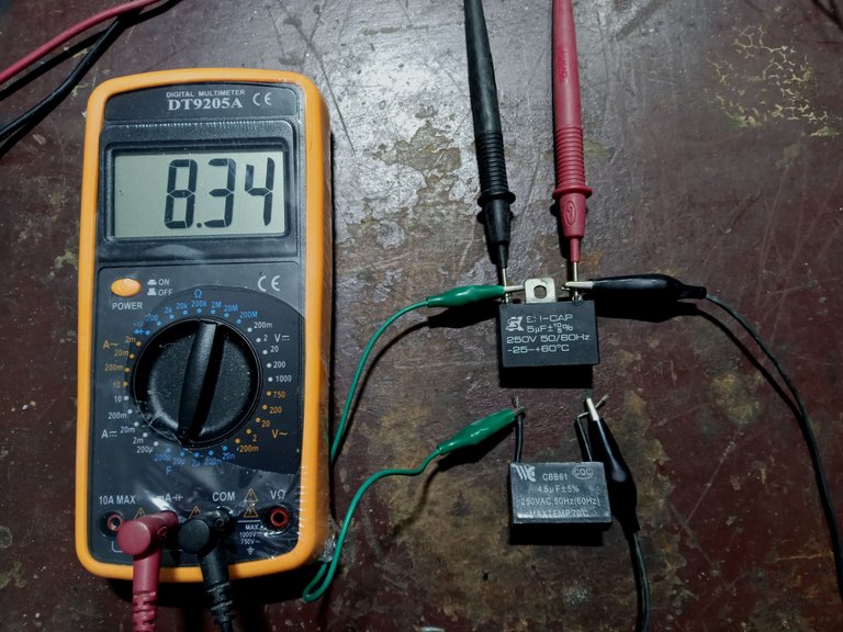
The trick to solving the problem is to use more than one capacitor. If you connect the capacitors in parallel, their values add up.
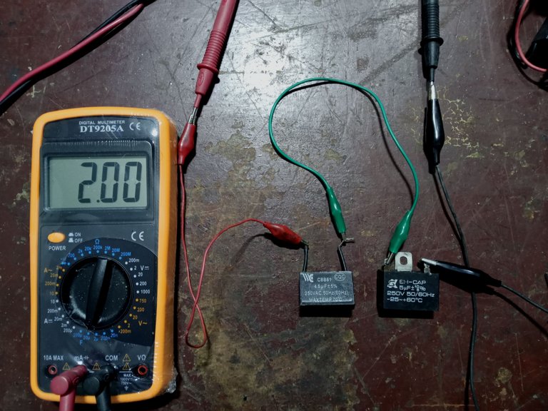
If you connect capacitors in series, their total values are the difference between the capacitors.
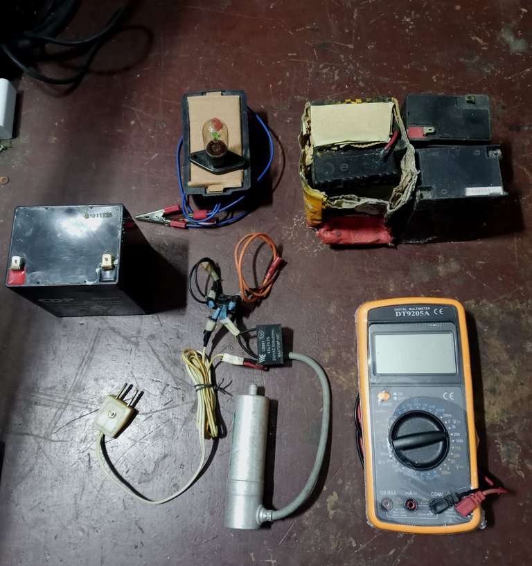
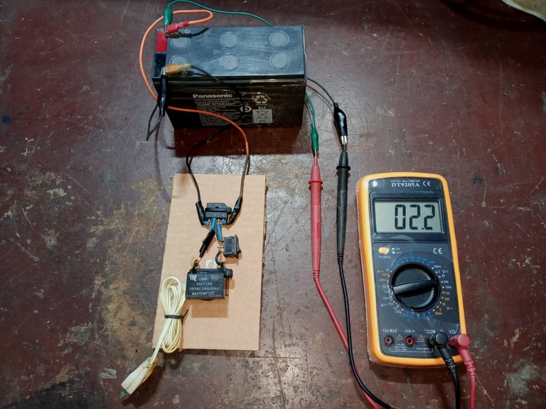
We need a capacitance meter or a tester that can measure capacitors. On some models, you need to change the position of the red probe.
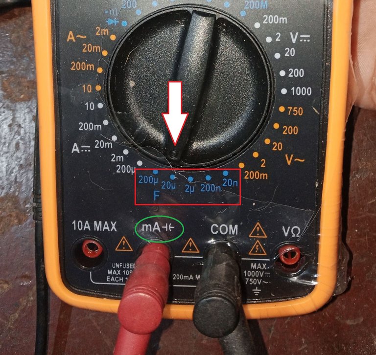
Each capacitor must be discharged before measuring them to avoid burning the tester or receiving an electric shock.
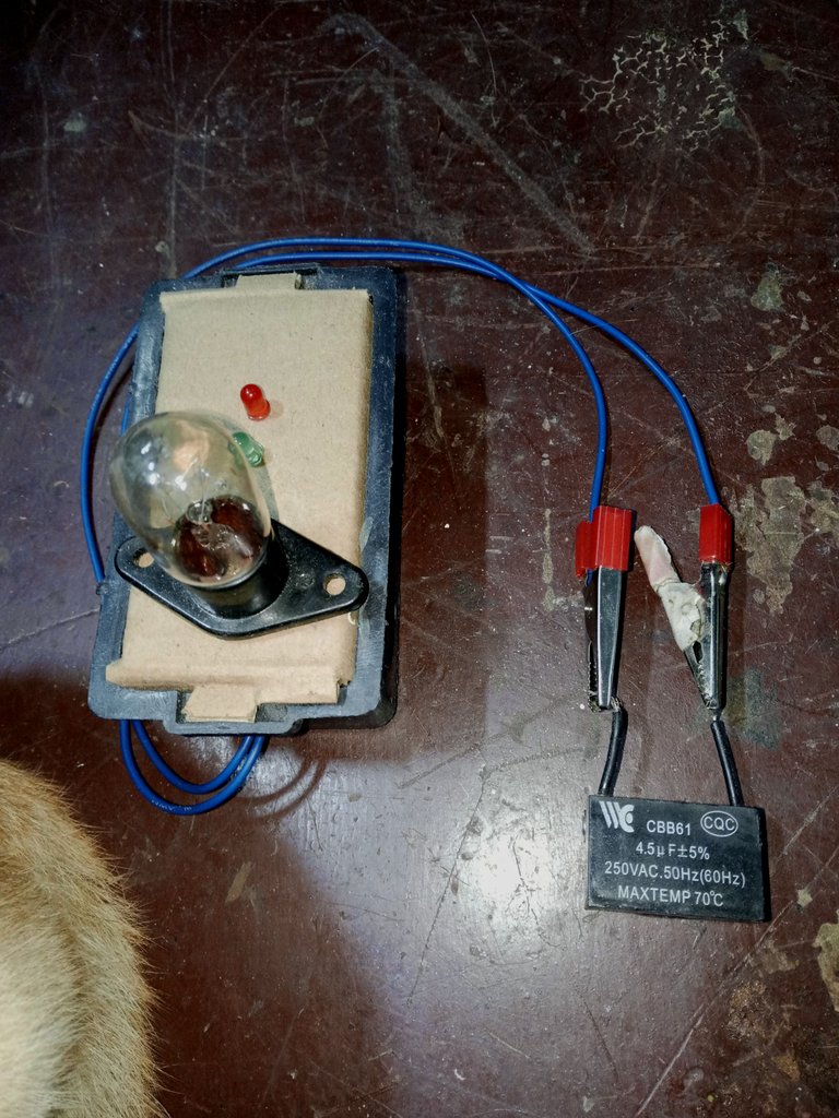
I use a circuit discharger tool, built with LEDs and a 110-volt microwave bulb.
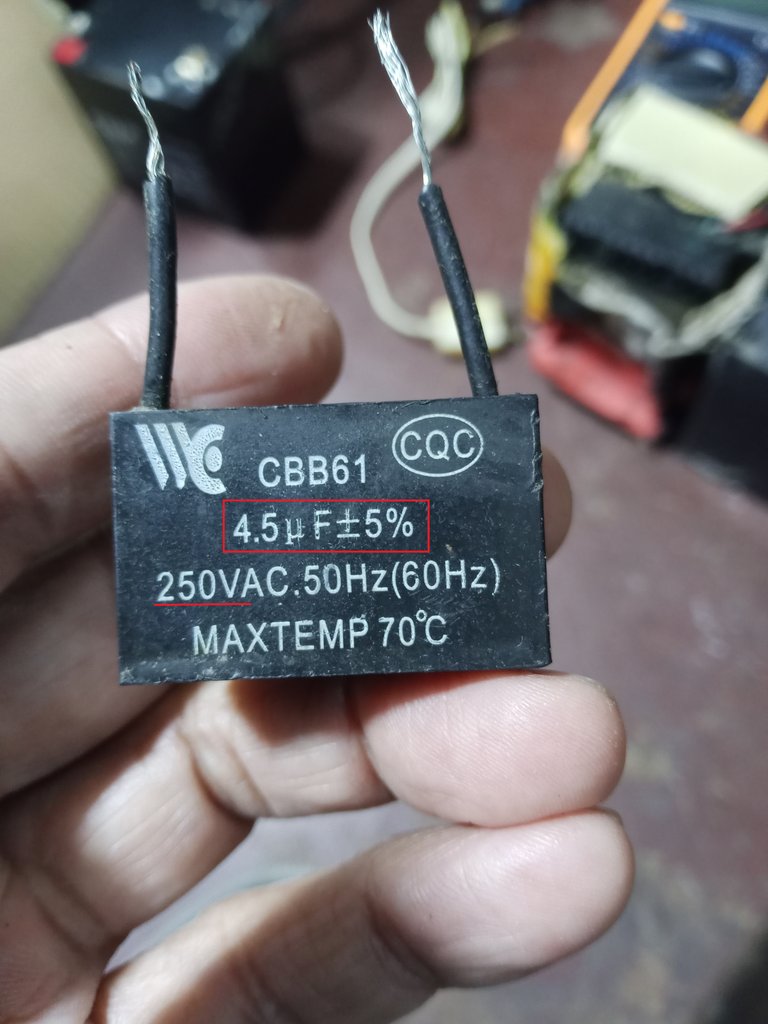
So, if I connect the capacitors in parallel, their values will add up. I used a 5 UF capacitor and a 4.5 UF capacitor to get close to the desired value.
If you connected the capacitors in series, the final value would be the subtraction of the total capacitors.
I'll use cardboard to make the base of the tool. To make it more sturdy, I'll build it in a crisscross pattern. I'll place one sheet of cardboard with the grain vertical, and the next layer will have the grain horizontal.
I'll secure the layers together with the hot glue gun.

With the base ready, we begin assembling the circuit.
I used some black plastic ties to secure the parts to the cardboard and prepared for testing. I added a switch that I recycled from a PC ATX power supply.
When you power the circuit, the tester indicates 119 volts DC at the battery terminals. As the battery charges, the voltage indicated by the tester will decrease.
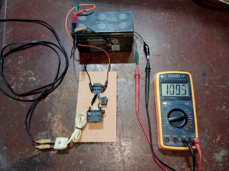
After half an hour of charging, the tester already indicated about 95 volts DC. When the battery is fully charged, the tester should indicate about 13 volts DC.

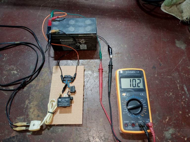
I briefly turned off the circuit to check how much charge the battery had gained after half an hour, and waited a few minutes to make sure the charge had been maintained.
The circuit is very simple, but there were some complications that prevented me from making good progress.
Once the complications were overcome, we were able to move forward with the construction.
Thank you so much for stopping by and reading.
Have a great week.
Peace.

- I used Google Translate for the English language.
- I used TextStudio for the Spanish header.
- The images, unless otherwise noted, are screenshots of my work in the workshop.
- I used the free online electrical circuit simulator MasterPLC for the electrical schematic.

Saludos, comunidad Hive Diy, espero que estén llenos de buen ánimo y esta nueva semana les sea productiva para que nos compartan publicaciones interesantes.
Tomo esta oportunidad para cumplir lo que les había prometido en mi anterior publicación de reparación de un UPS, que prometí que les explicaría como hacer y usar un sencillo recuperador de baterías casero.
En aquel momento armé un circuito recuperador de prueba, solo para verificar si se podía reciclar la batería vieja del UPS en que estaba trabajando.
Una aclaratoria importante: Si trabajan o van a manipular con este tipo de baterías, es necesario estar atento a:
- usar lentes de protección.
- Tapabocas o respiradores.
- Que la zona de trabajo esté bien ventilada.
Estas baterías contienen ácido y puede causar daños si cae en la piel o se respiran los vapores que se desprenden durante el proceso de reparación.
Estar atentos al costo de la baterías, si son muy económicas no vale la pena toda esta labor. En mi país, te venden la batería casi al mismo costo de comprar un UPS, por eso me tomo el trabajo de reciclarlas.
Una batería recargable descargada, en buen estado, cuando le verificamos el voltaje DC con el tester, nos debe dar un valor cercano a la mitad de su carga máxima.
Si la batería es de 12 volts DC, nos debe indicar cerca de 6 volts DC, marcar 1 volts DC o menos es una muy mala señal de sus posibilidades de recuperación.
Menos de 2 volts DC, no es muy alentador.
Finalmente, encontré en mi depósito una batería con más de 2 volts DC, la usaré para esta publicación, no está en el valor mínimo aceptable, pero me servirá para detallar las explicaciones.
En cuanto al circuito eléctrico, es muy básico, aprovecho un puente rectificador que recicle de un equipo de sonido antiguo, capacitores y cables recuperados de motores de electroventiladores reciclados.
Para trabajar con baterías de UPS, usar un capacitor con 8 Microfaradios es suficiente, para baterías de automóviles que son de un tamaño mayor, he visto usar capacitores de 45 Uf (45 Microfaradios)
El problema es que yo solo tenía un capacitores muy grandes o muy pequeños
, tenía un capacitor de 15 UF y capacitores de 4 Uf y de 5 Uf.
| |
|---|---|
El truco para resolver el problema es usar más de un capacitor, si conectas los capacitores en paralelo sus valores se suman.
Si conectas capacitores en serie, sus valores totales son la resta de los capacitores.
Necesitamos un capacímetro o un tester que tenga la función de medir capacitores, en algunos modelos hay que cambiar la posición de la sonda roja.
Y se debe descargar cada capacitor antes de medirlos, para evitar quemar el tester o para evitar recibir una descarga de electricidad.
Yo uso un descargador de circuitos, construido con leds y un bombillo de microondas de 110 Volts
Entonces, sí coloco los capacitores en conexión paralelo, sus valores se irán sumando. Use un capacitor de 5 Uf y uno de 4,5 Uf para acercarme al valor deseado.
Si conectara los capacitores en serie, el valor final sería la resta del total de los capacitores.
Usaré cartón para hacer la base de la herramienta, para hacer que la base sea más robusta, lo armaré de forma cruzada, una lámina de cartón la colocaré con las vetas verticales y la siguiente capa tendrá las vetas en posición horizontal.
Fijaré las capas entre sí con la pistola de silicona caliente.
Con la base lista, comenzamos a armar el circuito.
Aproveche unas abrazaderas plásticas negras para fijar las partes sobre el cartón y nos preparamos para las pruebas, agregue un interruptor que recicle de una fuente ATX de PC.
Cuando alimentas el circuito eléctrico, el tester indica 119 volts DC en los bornes de la batería, mientras la batería se va cargando ese voltaje que nos indica el tester irá reduciéndose.
Después de media hora de carga ya el tester indicaba unos 95 volts DC, cuando la batería esté completamente cargada, el tester debería indicar unos 13 volts DC.
Apague un momento el circuito para comprobar cuanta carga había ganado la batería, y espere unos minutos para asegurarme que la carga obtenida se mantenía.
El circuito es muy sencillo, pero hubo ciertas complicaciones para avanzar bien en el trabajo.
Superadas las complicaciones pudimos salir adelante con la construcción.
Muchas gracias por pasar y leerme.
Que tengan una excelente semana.
Paz.
- He usado el traductor de Google para el idioma inglés.
- Use el programa de TextStudio para el encabezado en español.
- Las imágenes a menos que lo indique son capturas de mi trabajo en el taller.
- Use el simulador de circuitos eléctricos en línea gratuito MasterPLC para el esquema eléctrico.
This post has been manually curated by @bhattg from Indiaunited community. Join us on our Discord Server.
Do you know that you can earn a passive income by delegating to @indiaunited. We share more than 100 % of the curation rewards with the delegators in the form of IUC tokens. HP delegators and IUC token holders also get upto 20% additional vote weight.
Here are some handy links for delegations: 100HP, 250HP, 500HP, 1000HP.
100% of the rewards from this comment goes to the curator for their manual curation efforts. Please encourage the curator @bhattg by upvoting this comment and support the community by voting the posts made by @indiaunited.
Many thanks to friend @bhattg and the people of the @indiaunited community, for their support.
Have good health and a quiet week.
¿ᴺᵉᶜᵉˢᶦᵗᵃˢ ᴴᴮᴰ? ᵀᵉ ˡᵒ ᵖʳᵉˢᵗᵃᵐᵒˢ ᶜᵒⁿ @ruta.loans
Thanks to the @rutablockchain community for support.
Have an excellent week.
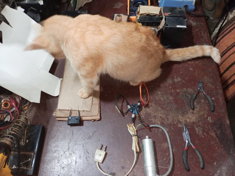
Un trabajo interesante, bueno para las ideas de reciclaje, y es un toque gracioso el tener al gato en la mesa obstaculizando el trabajo un poco.
!BBH !BEER !PIZZA !ALIVE
De tanto tenerlo en el taller, el gato va a terminar aprendiendo a soldar circuitos y a reparar TV.
Eso haría que fuera un gato mucho más raro de lo que ya es 😅👍😸
$PIZZA slices delivered:
@pedrobrito2004(3/5) tipped @soltecno
Come get MOONed!
Muchas gracias por el detalle @pedrobrito2004.
Hola hermano saludos. Interesante tu trabajo, tengo unas cuantas de esas listas para recuperar, he realizado otros métodos para lograr esa recuperación, sin embargo no siempre he podido lograr la recuperación. Esta vía que has comentado me parece interesante, la pondré en práctica. Gracias por compartir. Saludos
Gracias por pasar y comentar amigo, no siempre se logran recuperar las baterías, pero con un circuito tan simple, creo que vale la pena hacer la prueba.
Hay un montón de métodos que no comparto, porque tienen que manipular ácido, o colocar sal en las baterías, no es fácil como se ven en algunos videos. Se necesita un medidor de densidad para colocar el ácido justo en los vasos de la batería, no es algo que cualquiera pueda hacer sin riesgo.
Disculpa por responder tarde, algunos días se me complican un poco las tareas.
Así es hermano, no todos los métodos son tan simples y algunos más riesgosos que otros. Saludos
Yo aqui en mi ignorancia corazon, me encantan tus proyectos, pero dime si ese es un capacitor de los que usan los ventiladores (aunque no se si lleva otro nombre) hablo del color negro, me impresiona verlo en un ups. Por cierto al mio la bateria ya expiro :(
Saludos, si es un capacitor de ventilador común, son capacitores de marcha, no tienen polaridad.
Lo importante es estar en los rangos de 8 Microfaradios para una batería de un UPS, tengo unos tres UPS en el depósito, voy a tratar de ir arreglando y publicando, puede que alguno tenga la falla de tu UPS, y te sirva.
Disculpa por responderte tan tarde, he estado bastante atareado, con tantos problemas a diario, uno nunca se aburre en este país.
Cuídese y que pasen una semana tranquila, en la medida de lo posible.
Congratulations @soltecno! You have completed the following achievement on the Hive blockchain And have been rewarded with New badge(s)
Your next target is to reach 8500 comments.
You can view your badges on your board and compare yourself to others in the Ranking
If you no longer want to receive notifications, reply to this comment with the word
STOPGreetings, as always: thank you so much for stopping by to say hello.
I didn't realize there were already so many comments, so now we'll try to reach the next milestone.