[EN/PT] Electric motor fault detector
[EN]
I recently started a master's degree in Electrical Engineering, focusing on research into the early detection of faults in electric motors — before these faults manifest themselves critically in the equipment. The basis of the research is an algorithm developed by Mateus Ventura, aimed at detecting faults in the rotor bars of three-phase asynchronous induction motors (MIT).
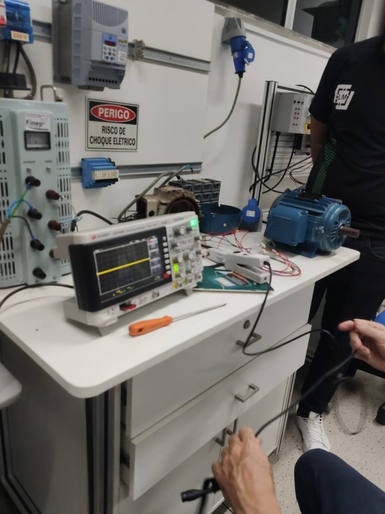
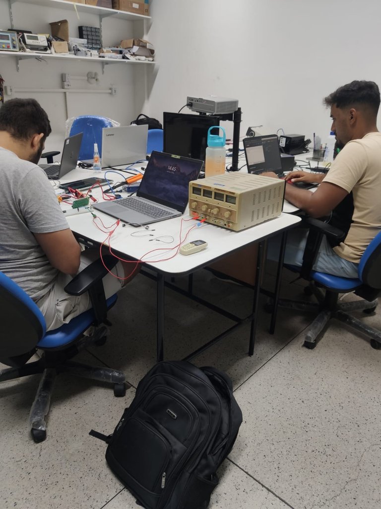
The MIT can be seen in the image below (in blue, on the workbench). Ventura's work was developed in partnership with WEG S.A., with the aim of identifying faults in the rotor bars — the moving part of the motor — during the manufacturing process.
Currently, the proposal is to expand the application of this algorithm, integrating it with other diagnostic methods to detect a wider range of faults in motors used in electric vehicles. Among the faults to be analyzed are: shaft imbalance, bearing wear, misalignment, among others, of both a mechanical and electrical nature. To do this, the motor's current and voltage signals are used, applying Electrical Signature Analysis (ESA) techniques, which allow the identification of patterns characteristic of these faults in the frequency spectrum.
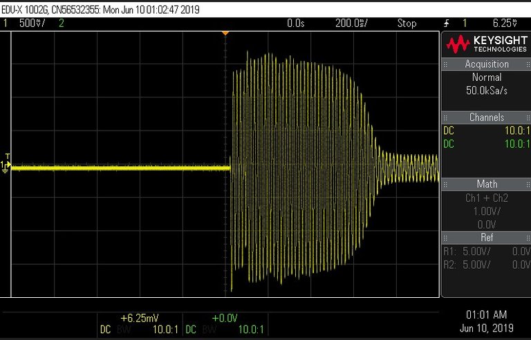
The following image shows the experimental setup used to acquire the current signal during electric motor start-up. At this stage, the starting current can reach 8 to 10 times the nominal current value, which is the region of greatest interest for the proposed analysis. For the measurement, an oscilloscope and a clamp-type probe are used, which allows for accurate capture of the motor current signal.
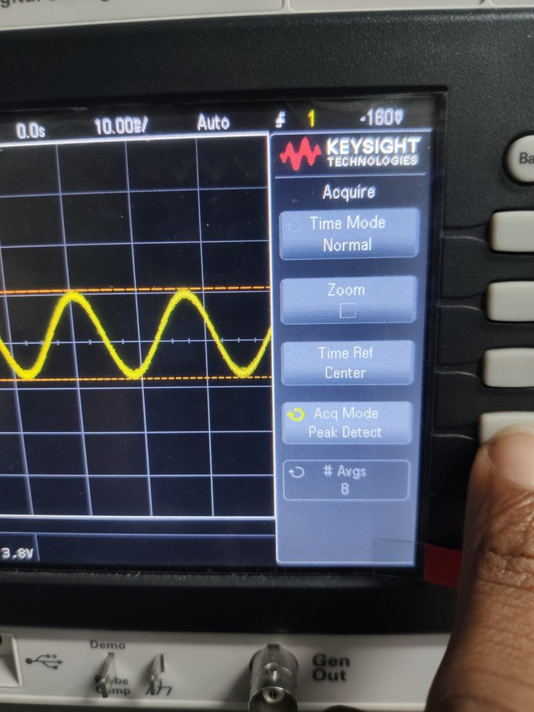
During normal operation, the motor's electrical current is a continuous sine wave with a fundamental frequency of 60 Hz and an amplitude corresponding to the rated current, which remains practically constant. However, during motor start-up, this behavior changes significantly. The current starts with a high peak and decays rapidly until it reaches the rated value, forming a characteristic envelope profile. This behavior can be visualized as a gently decreasing curve, with a shape similar to that of an inverted parabola. In the motor under analysis, the starting current reaches approximately 8 amperes, representing 8 to 10 times the rated current, which characterizes one of the most critical and relevant regions for current signature fault analysis.
The current signal acquired during engine start-up is originally in the time domain. However, for fault analysis, it is necessary to convert it to the frequency domain, where the so-called “frequency signatures” become visible — specific spectral components that indicate the presence and type of fault. To do this, the starting current signal is stored on a USB flash drive and later processed by an algorithm that uses digital filters, notably the Gaussian filter. After applying this filter, the signal reveals distinct characteristic behaviors between motors with healthy rotors and those with different types and intensities of faults.
It is worth noting that the research includes several rotors in different conditions, covering different degrees of structural faults. This allows the acquisition of multiple representative samples, enabling effective comparisons and contributing to the robustness of the diagnostic process.
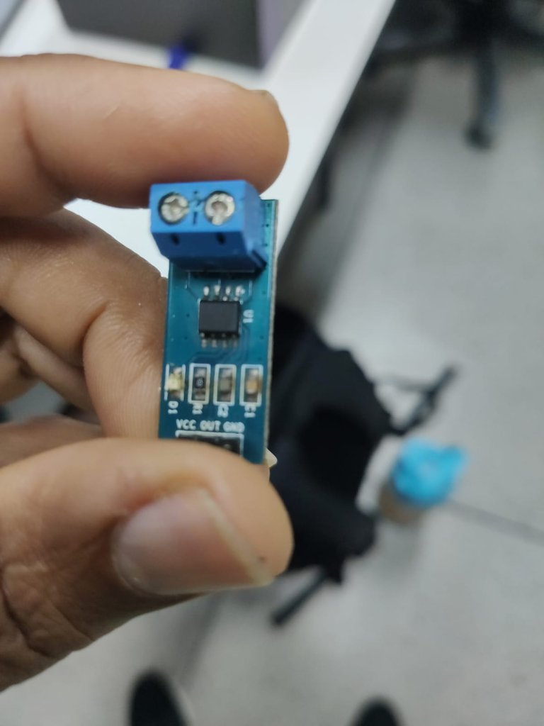
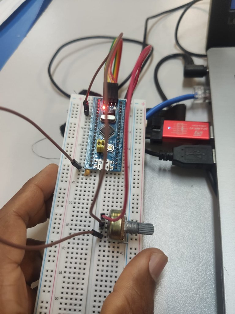
However, the main proposal of this project is to replace the use of laboratory equipment, such as oscilloscopes and current probes, with a more practical embedded solution applicable to electric vehicles in real operation. The idea is to develop a microcontroller-based acquisition system using a Hall effect current sensor. The sensor adopted is the ACS712 model 30A, known for its good linearity, which makes it very suitable for accurate current measurements in embedded applications.
In the first acquisitions made with the PIC16F877A microcontroller, the results obtained in the current reading during engine start-up were not satisfactory. The main limitation observed was the low resolution of the microcontroller's analog-to-digital converter (ADC), which has only 10 bits. As the motor starts very quickly, the number of samples collected at high speed and with the resolution necessary to capture the details of the signal was not sufficient.
This limitation resulted in a significant loss of information in the acquired signal. When compared to the waveform captured by an oscilloscope, it can be seen that the signal obtained by the microcontroller does not adequately represent the actual starting current. The waveform is distorted and lacks the typical characteristics observed in the time domain, thus compromising the effectiveness of fault analysis.
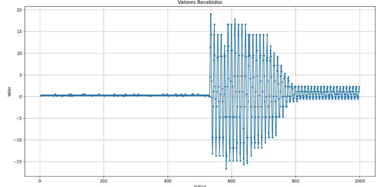
Given the limitations observed with the PIC16F877A microcontroller, we opted to use the STM32F103C8T6, which offers significantly superior performance for this application. One of the main differences is its analog-to-digital converter (ADC) with 12-bit resolution, which allows for greater precision in reading current signals, especially during the critical engine start-up phase.
At the time of writing, I am studying the features of this microcontroller, focusing on the implementation of an efficient and reliable current acquisition system. Wish me luck in this endeavor!
I hope you enjoyed this post! I know it ended up being a little more technical than usual, but I thought it was important to share these details about the project. I'll be back soon with more news about the progress and discoveries on this journey!
Images: Personal Archive

[PT]
Recentemente, iniciei o mestrado em Engenharia Elétrica com foco em uma pesquisa voltada à detecção precoce de falhas em motores elétricos — antes mesmo que essas falhas se manifestem de forma crítica no equipamento. A base da pesquisa é um algoritmo desenvolvido por Mateus Ventura, voltado à detecção de falhas nas barras do rotor de motores de indução trifásicos assíncronos (MIT).
O MIT pode ser observado na imagem abaixo (em azul, sobre a bancada). O trabalho de Ventura foi desenvolvido em parceria com a WEG S.A., com o objetivo de identificar falhas nas barras do rotor — a parte móvel do motor — ainda durante o processo de fabricação.
Atualmente, a proposta é expandir a aplicação desse algoritmo, integrando-o a outros métodos de diagnóstico, para detectar uma gama mais ampla de falhas em motores utilizados em veículos elétricos. Entre as falhas a serem analisadas estão: desbalanceamento do eixo, desgaste dos rolamentos, desalinhamento, entre outras, de natureza tanto mecânica quanto elétrica. Para isso, são utilizados os sinais de corrente e tensão do motor, aplicando-se técnicas de análise por assinatura elétrica (Electrical Signature Analysis — ESA), as quais permitem identificar padrões característicos dessas falhas no espectro de frequência.
A imagem a seguir apresenta o setup experimental utilizado para aquisição do sinal de corrente durante a partida do motor elétrico. Nesse estágio, a corrente de partida pode atingir de 8 a 10 vezes o valor da corrente nominal, sendo essa a região de maior interesse para a análise proposta. Para a medição, são utilizados um osciloscópio e uma sonda tipo garra, que permite a captura precisa do sinal de corrente do motor.
Durante o regime permanente de operação, a corrente elétrica do motor apresenta-se como uma forma de onda senoidal contínua, com frequência fundamental de 60 Hz e amplitude correspondente à corrente nominal, que se mantém praticamente constante. No entanto, durante a partida do motor, esse comportamento se altera significativamente. A corrente inicia-se com um pico elevado e decai rapidamente até atingir o valor nominal, formando um perfil característico de envoltória. Esse comportamento pode ser visualizado como uma curva suavemente decrescente, com formato semelhante ao de uma parábola invertida. No motor em análise, a corrente de partida atinge aproximadamente 8 amperes, representando de 8 a 10 vezes a corrente nominal, o que caracteriza uma das regiões mais críticas e relevantes para a análise de falhas por assinatura de corrente.
O sinal de corrente adquirido durante a partida do motor está originalmente no domínio do tempo. No entanto, para a análise de falhas, é necessário convertê-lo para o domínio da frequência, onde se tornam visíveis as chamadas “assinaturas de frequência” — componentes espectrais específicas que indicam a presença e o tipo de falha. Para isso, o sinal de corrente de partida é armazenado em um pen drive e processado posteriormente por um algoritmo que emprega filtros digitais, com destaque para o filtro gaussiano. Após a aplicação desse filtro, o sinal revela comportamentos característicos distintos entre motores com rotores saudáveis e aqueles com diferentes tipos e intensidades de falhas.
Vale ressaltar que a pesquisa conta com diversos rotores em condições distintas, abrangendo diferentes graus de falhas estruturais. Isso permite a aquisição de múltiplas amostras representativas, possibilitando comparações eficazes e contribuindo para a robustez do processo de diagnóstico.
Contudo, a proposta principal deste projeto é substituir o uso de equipamentos laboratoriais, como o osciloscópio e a sonda de corrente, por uma solução embarcada mais prática e aplicável a veículos elétricos em operação real. A ideia é desenvolver um sistema de aquisição baseado em microcontrolador, utilizando um sensor de corrente do tipo efeito Hall. O sensor adotado é o ACS712 modelo 30A, conhecido por sua boa linearidade, o que o torna bastante adequado para medições precisas de corrente em aplicações embarcadas.
Nas primeiras aquisições realizadas com o microcontrolador PIC16F877A, os resultados obtidos na leitura de corrente durante a partida do motor não foram satisfatórios. A principal limitação observada foi a baixa resolução do conversor analógico-digital (ADC) do microcontrolador, que possui apenas 10 bits. Como a partida do motor ocorre de forma muito rápida, a quantidade de amostras coletadas em alta velocidade e com a resolução necessária para captar os detalhes do sinal não foi suficiente.
Essa limitação resultou em perda significativa de informações no sinal adquirido. Ao comparar com a forma de onda capturada por um osciloscópio, percebe-se que o sinal obtido pelo microcontrolador não representa adequadamente a corrente real de partida. A forma de onda apresenta-se distorcida e sem as características típicas observadas no domínio do tempo, comprometendo assim a eficácia da análise de falhas.
Diante das limitações observadas com o microcontrolador PIC16F877A, optamos por utilizar o STM32F103C8T6, que apresenta um desempenho significativamente superior para essa aplicação. Um dos principais diferenciais é o seu conversor analógico-digital (ADC) com resolução de 12 bits, o que permite maior precisão na leitura dos sinais de corrente, especialmente durante a fase crítica de partida do motor.
No momento da redação deste texto, estou me dedicando ao estudo das funcionalidades desse microcontrolador, com foco na implementação de um sistema de aquisição de corrente eficiente e confiável. Me desejem sorte nessa empreitada!
Espero que tenha gostado deste post! Sei que ele acabou ficando um pouco mais técnico do que o habitual, mas achei importante compartilhar esses detalhes do projeto. Em breve, volto com mais novidades sobre os avanços e descobertas nessa jornada!
Imagens: Arquivo Pessoal
Posted Using INLEO
Obrigado por promover a comunidade Hive-BR em suas postagens.
Vamos seguir fortalecendo a Hive
https://x.com/ElderCleiton/status/1938434614248309089
Congratulations @elderdark! You have completed the following achievement on the Hive blockchain And have been rewarded with New badge(s)
Your next payout target is 15000 HP.
The unit is Hive Power equivalent because post and comment rewards can be split into HP and HBD
You can view your badges on your board and compare yourself to others in the Ranking
If you no longer want to receive notifications, reply to this comment with the word
STOPCheck out our last posts:
Thanks for your contribution to the STEMsocial community. Feel free to join us on discord to get to know the rest of us!
Please consider delegating to the @stemsocial account (85% of the curation rewards are returned).
Consider setting @stemsocial as a beneficiary of this post's rewards if you would like to support the community and contribute to its mission of promoting science and education on Hive.
Thank you!