HOW TO REPAIR PC KEYBOARD.//COMO REPARAR EL TECLADO DE LA PC .[EN-ES]
ENGLISH
Hello my friends, I hope everyone is well. Lately I have not had the opportunity to interact in the community, the repeated and prolonged blackouts that we have here do not allow me to do so. These days the situation is slightly improving, at least in the area where I live, and well, here I am sharing with the community one of those problems that sometimes we have at home and that we can solve in some way with our own hands.
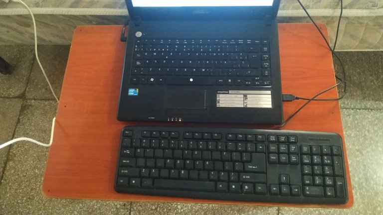
I tell you that the USB keyboard I use to work on the laptop stopped working. When I connected it to the USB port it did not give any signal, it did not turn on any of its indicator LEDS. This keyboard is a membrane keyboard and from now on everything I will say will be related to these types of keyboards.
When checking the device manager in the laptop settings, no USB keyboard was recognized even though it was physically connected.
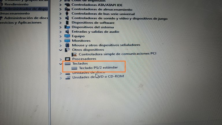
Here you can see that only the original laptop keyboard is recognized.
After verifying that the USB ports of the laptop were in good condition, I decided to check the keyboard in depth, because without it I cannot work, since the laptop has some damaged keys on its original keyboard.
STEP BY STEP
- The first thing I did was to perform a visual inspection of the keyboard cable for any physical damage.
- Then it was necessary to open the keyboard with the help of a screwdriver.
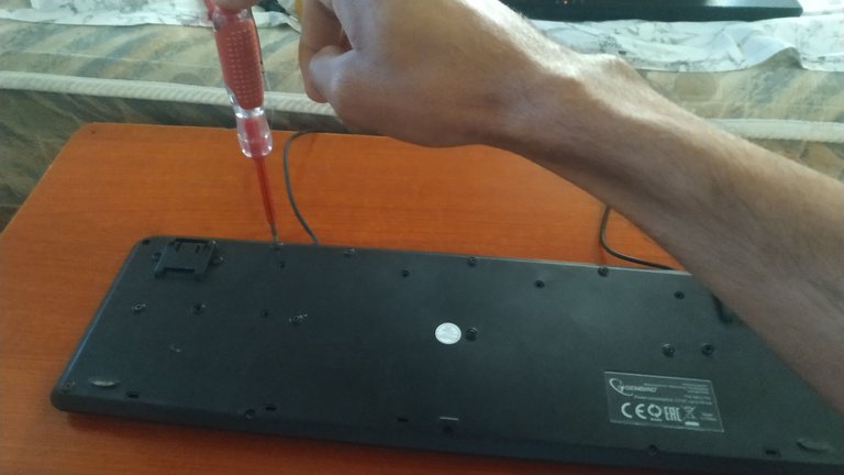
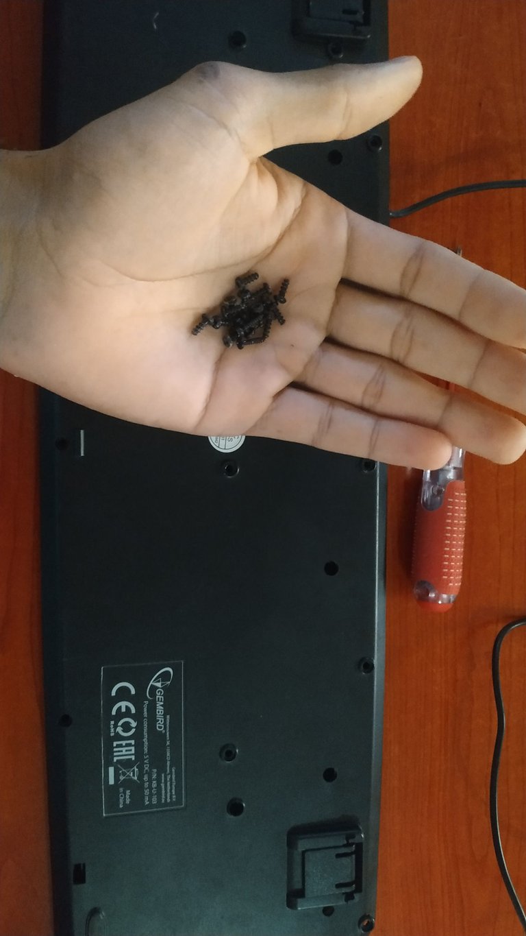
- After removing the screws, the back cover is carefully removed, exposing the keyboard membrane. This membrane is composed of three flexible sheets forming a sandwich where the upper and lower sheets contain tracks and conductive points, the central sheet is responsible for isolating the two upper and lower sheets, preventing contact between the conductive points while no key is pressed, the central sheet has holes in the positions of each key and when pressing any of them the upper sheet is deformed and makes contact with the lower sheet through the hole in the central sheet.
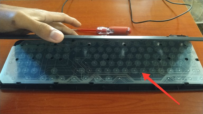
Keypad membrane
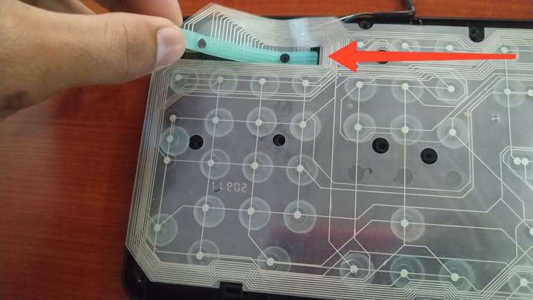
- The next step was to remove the membrane from the keyboard by disconnecting it from its connection point.
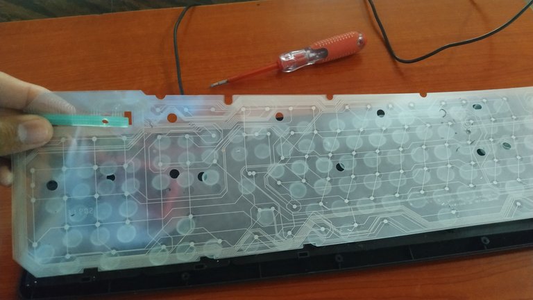
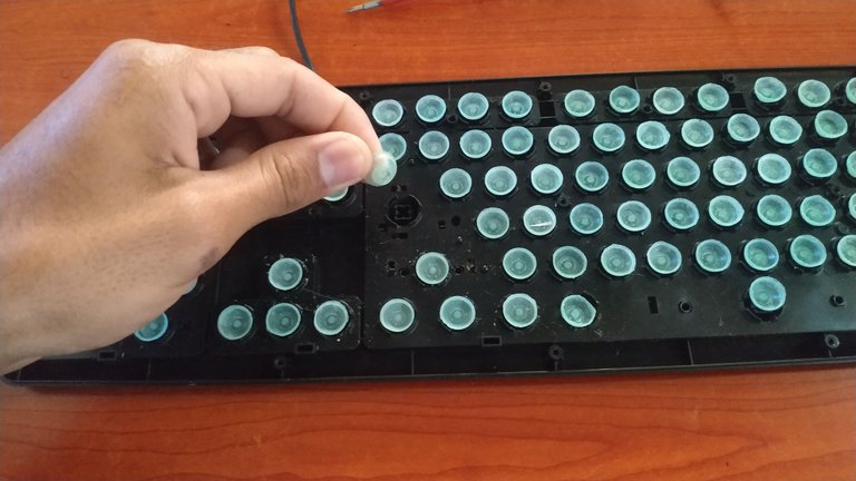
These are the rubber domes and are responsible for providing resistance so that the keys return to their place after being pressed. In addition, the keystroke is achieved through them by joining the membrane sheets.
Care should be taken with the rubber domes and keys, as they are loose and can easily fall off.
- After removing the membrane, it remains to remove the keyboard controller board, which is responsible for processing the electrical signals generated by pressing the keys and then send them to the computer through the USB cable to be interpreted.
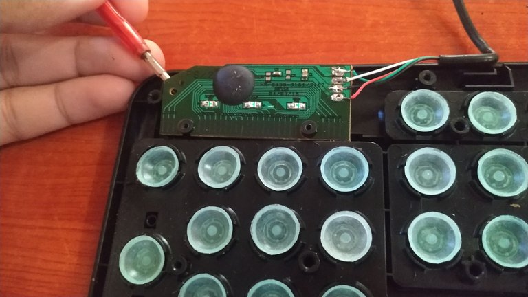
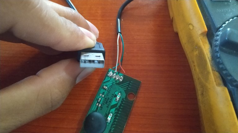
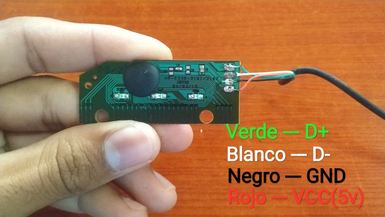
Here are the connections of the USB cable to the board, the red wire corresponds to the 5 Volt power supply, the black wire is the ground (GND), the white wire corresponds to the D- connection (negative data) of the data transmission line, the green wire corresponds to D+ (positive data) of the data transmission line.
- After visually checking the controller board and not detecting any physical damage, the next step was to measure the continuity of each of the wires from one end to the other, for that it is necessary to have a multimeter and select the scale of continuity or resistance and with the tips of the multimeter we make contact between the ends of each wire, as shown in the following images.

USB connector pins
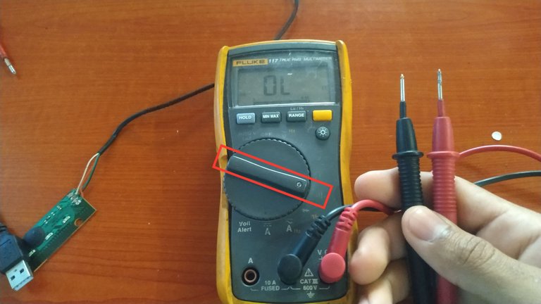
Select the continuity scale on the multimeter
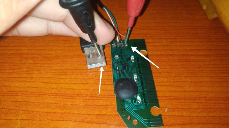
Measure continuity between the ends of the red wire, in this case one end of the multimeter is connected to pin 1 of the USB connector and the other end is connected to the other end of the red wire (VCC).
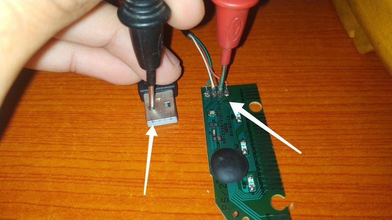
Measure continuity between the ends of the black cable, in this case, one of the tips of the multimeter makes contact with pin 4 of the USB connector and the other tip makes contact with the other end of the black cable (GND).
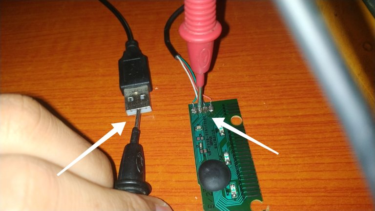
Measure continuity between the ends of the white cable, in this case one of the tips of the multimeter makes contact with pin 2 of the USB connector and the other tip makes contact with the other end of the white cable (D-).
The green wire (D+) is measured in the same way as described for the white wire (D-).
After measuring the four wires, I detected that there was no continuity in the white wire where the negative data are transported, this means that there is a break in some section of this wire.
Once the cause of the problem has been determined, the next step is to solve it. To do this we must detect where the cable is interrupted, cut and solder again to the board.
Luckily to determine the position where the cable was broken was easy, I only had to unsolder the wires from the board, and taking into account that the most vulnerable part of the cable is in the position where it bends inside the keyboard and is pressed by the covers of the same, I suspected that there would be the interruption.
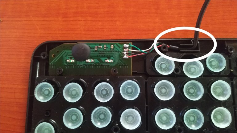
At this point some of the cables usually break off
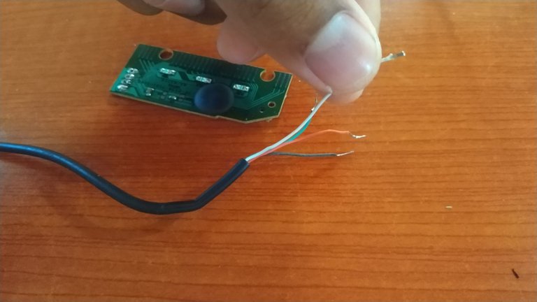
Pulling gently on the white wire, it came out without any problem, as it was broken.
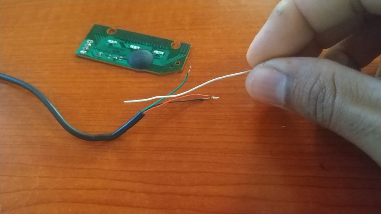
Here is the cause of the problem.
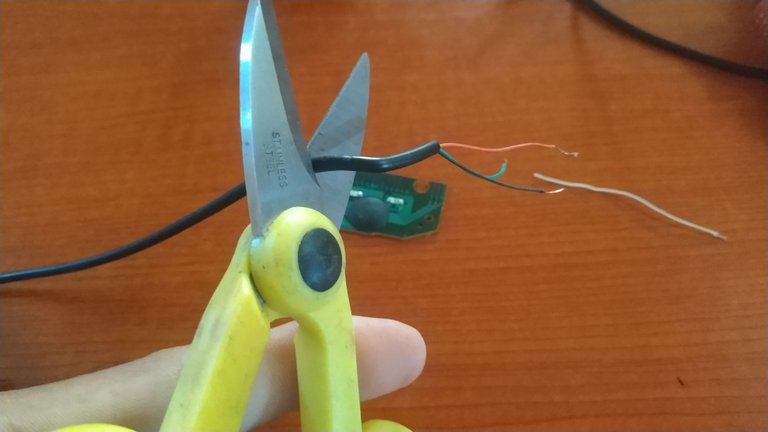
Cut a further back section where the cable was broken
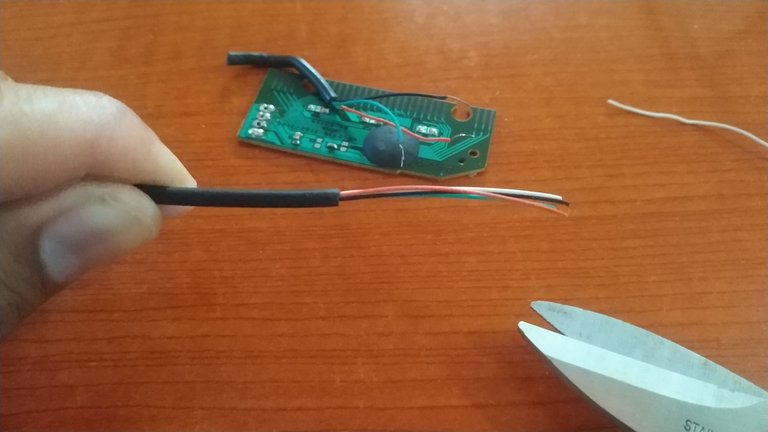
Removing the insulation from the cables
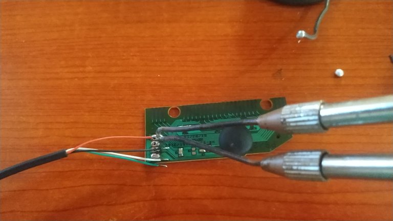
Re-solder the wires in the same order as before.
After soldering I check by connecting the cable to the laptop and it was automatically recognized by the operating system.
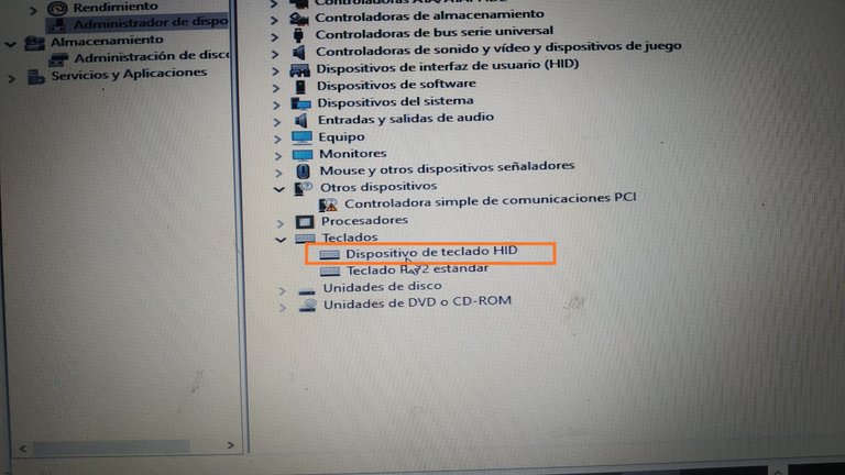
Here you can see how the keyboard controller board has already been recognized.
Ready!!!, it only remains to reassemble the keyboard and work with it.
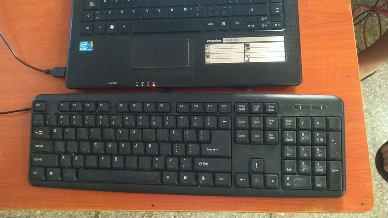
It turns out that there was no communication between the laptop and the controller board due to a break in one of the data transmission cables. This problem is common, and its solution is relatively simple. I hope that what I have shared here at least serves as a reference and basis for understanding what might be going on with your keyboard if it has the same symptoms I described above.
Greetings to everyone and until next time.😉
The photos were taken with my Xiaomi Redmi Note 6 Pro cell phone.
*Cover edited in "Canva" and photo editing in my phone's Gallery app.
Text translated to English in Deepl translator.
You can see me at Facebook
ESPAÑOL
Hola mis amigos, espero que todos estén bien. Últimamente no he tenido oportunidad de interactuar en la comunidad, los apagones reiterados y prolongados que tenemos acá no me lo permiten. En estos días la situación está con una leve mejoría, al menos en la zona donde vivo, y bueno, acá estoy compartiendo con la comunidad uno de esos problemas que a veces tenemos en casa y que podemos resolver en cierta media con nuestras propias manos.
Les comento que el teclado USB que utilizo para trabajar en la laptop dejó de funcionar. Al conectarlo al puerto USB no daba señales de ningún tipo, no encendía ninguno de sus LEDS indicadores. Este teclado es de membrana y en lo adelante todo lo que diré será en relación con estos tipos de teclados.
Al revisar el administrador de dispositivos en los ajustes de la laptop, no aparecía ningún teclado USB reconocido a pesar de estar conectado físicamente.

Acá se observa que solo se reconoce el teclado original de la laptop
Después de verificar que los puertos USB de la laptop estaban en buenas condiciones, me decidí a revisar en profundidad el teclado, pues sin él no puedo trabajar, ya que la laptop tiene algunas teclas dañadas en su teclado original.

PASO A PASO
- Lo primero que hice fue realizar una inspección visual del cable del teclado en busca de cualquier desperfecto físico.
- Luego fue necesario abrir el teclado con ayuda de un destornillador.


- Después de remover los tornillos, con mucho cuidado se retira la tapa trasera, y queda expuesta la membrana del teclado. Esta membrana está compuesta por tres láminas flexibles formando un sándwich donde la lámina superior e inferior contienen pistas y puntos conductores, la lámina central se encarga de aislar las dos láminas superior e inferior, evitando el contacto entre los puntos conductores mientras no se presione ninguna tecla, la lámina central tiene agujeros en las posiciones de cada tecla y al presionar alguna de ellas la lámina superior se deforma y hace contacto con la lámina inferior a través del agujero de la lámina central.

Membrana del teclado
- Lo siguiente fue retirar la membrana del teclado desconectándola de su punto de conexión.


Estas son las cúpulas de goma y se encargan de ofrecer una resistencia para que las teclas retornen a su lugar después de ser presionadas. Además, a través de ellas se logra la pulsación mediante la unión de las láminas de la membrana.
Hay que tener cuidado con las cúpulas de goma y las teclas, pues están sueltas y se pueden caer con facilidad.
- Después de retirar la membrana, queda retirar la placa controladora del teclado, la cual se encarga de procesar las señales eléctricas generadas al presionar las teclas y que luego enviará a la computadora a través del cable USB para que sean interpretadas.


Aquí se observan las conexiones del cable USB a la placa, el cable rojo corresponde al los 5 Volt de alimentación, el negro es la tierra (GND), el cable blanco corresponde con la conexión D- (Datos negativos) de la línea de transmisión de datos, el cable verde corresponde con D+ (datos positivos) de la línea de transmisión de datos.
- Después de chequear visualmente la placa controladora y no detectar ningún desperfecto físico, lo siguiente fue medir la continuidad de cada uno de los cables desde un extremo al otro, para eso es necesario contar con un multímetro y seleccionar la escala de continuidad o resistencia y con las puntas del multímetro hacemos contacto entre los extremos de cada cable, de la forma que mostraré en las siguientes imágenes.

Pines del conector USB

Seleccionar la escala de continuidad en el multímetro

Medir continuidad entre los extremos del cable Rojo , en este caso se hace contacto con una de las puntas del multímetro al pin 1 del conector USB y la otra punta hace contacto con el otro extremo del cable rojo (VCC).

Medir continuidad entre los extremos del cable Negro , en este caso se hace contacto con una de las puntas del multímetro al pin 4 del conector USB y la otra punta hace contacto con el otro extremo del cable negro (GND)

Medir continuidad entre los extremos del cable Blanco , en este caso se hace contacto con una de las puntas del multímetro al pin 2 del conector USB y la otra punta hace contacto con el otro extremo del cable blanco (D-)
La medición del cable verde (D+) se hace de la misma forma descrita para el cable blanco (D-).
Después de realizar las mediciones de los cuatro cables, detecté que no había continuidad en el cable blanco por donde se transportan los datos negativos, esto quiere decir que hay una rotura en algún tramo de este cable.
Determinada la causa del problema, lo siguiente es darle solución. Para eso hay que detectar dónde está interrumpido el cable, cortar y soldar nuevamente a la placa.
Por suerte determinar la posición donde estaba partido el cable fue fácil, solo tuve que desoldar los cables de la placa, y teniendo en cuenta que la parte más vulnerable del cable es en la posición donde se dobla en el interior del teclado y queda presionada por las tapas del mismo, sospeché que ahí estaría la interrupción.

En este punto suelen partirse algunos de los cables

Tirando suavemente del cable blanco, este salió sin ningún problema, ya que estaba partido

Aquí está la causa del problema

Cortar un tramo más atrás donde se partió el cable

Quitar el aislante de los cables

Soldar nuevamente los cables en el mismo orden que estaban
Después de soldar hago la comprobación conectando el cable a la laptop y automáticamente fue reconocida por el sistema operativo.

Aquí se puede ver cómo ya fue reconocida la placa controladora del teclado
¡Listo!!!, solo queda armar nuevamente el teclado y a trabajar con él.


Resulta que no había comunicación entre la laptop y la placa controladora por la interrupción en uno de los cables de transmisión de datos. Este problema es común, y su solución es relativamente sencilla. Espero que lo que he compartido aquí sirva al menos de referencia y base para entender lo que pudiera estar pasando en tu teclado si presenta los mismos síntomas que describí anteriormente.
Un saludo para todos y hasta la próxima.😉
Las fotos fueron tomadas con mi celular Xiaomi Redmi Note 6 Pro.
Portada editada en "Canva" y edición de fotos en la app Galería de mi teléfono.
Puedes verme en Facebook
A quick and simple repair but very effective. I wish all were like this. Luckily, it was a problem with the cable and not one of the membrane lines. Thank you for sharing such a useful tutorial. Regards.
Si hermano, ya cuando el problema es en las lineas de la membrana la cosa es más complicado, se necesita pintura conductora para reparar, claro si el daño no es muy grande porque me he topado con membranas que ya no vale la pena tratar de reparar. Gracias por comentar hermano, saludos
Congratulations @darknapol! You have completed the following achievement on the Hive blockchain And have been rewarded with New badge(s)
Your next target is to reach 7000 upvotes.
You can view your badges on your board and compare yourself to others in the Ranking
If you no longer want to receive notifications, reply to this comment with the word
STOPMe viene muy bien su publicación, tengo varios teclados en el depósito, esperando por ser reparados o reciclados.
Me paso igual con una laptop, que tenía teclas dañadas, era más práctico colocar un teclado que comprar el repuesto, aunque sigo tratando de buscar un método para repara el teclado dañado.
Los tutoriales del YouTube hacen ver todo de las reparaciones muy fácil, pero cuando tratas de aplicar algunos de esos métodos como guía para los teclados de laptop, te das cuenta de que no siempre son métodos muy efectivos.
Hola hermano, la verdad esas membranas cuando se interrumpen las conexiones hay que tener pintura conductora para reparar, pero sinceramente ese trabajo no me gusta mucho hacerlo, a veces el daño es tanto que no vale la pena sinceramente. Preferí buscar un teclado antes de ponerme a tratar de reparar el de la laptop, pus se que ya es bastante viejito jj. Gracias por pasar y comentar. Saludos hermano
Con lo económico que se consiguen los teclados adicionales, no vale la pena el gasto de materiales y tiempo arreglando los teclados de laptop.
Sin embargo, en algún momento debo resolver lo del teclado del laptop.
@darknapol, I paid out 0.112 HIVE and 0.026 HBD to reward 2 comments in this discussion thread.
¡Qué maravilla de post tan útil!
¡Gracias!
Hola muchas gracias por tus palabras, me alegra que te haya gustado. Saludos, pasa una excelente noche.
Muchas gracias.
¡Lo propio!